How do you keep a robot arm safe, when safe depends on what it's holding?
A cup of water mustn't pass over a laptop, even with plenty of air to spare. A dry sponge can. This page explains, step by step, the maths that makes a robot arm behave this way. You can drag and change the diagrams as you read.
It's what I learned rebuilding, in simulation, the method of Brunke et al., "Semantically Safe Robot Manipulation" (IEEE Robotics and Automation Letters, 2025).
- The big picture
- Boundary
- Superquadrics
- Approach limit
- QP
- The trap
- Semantic regions
- Franka inverse kinematics
- Whole arm
- The full filter
The big pictureA filter between the controller and the robot
A safety filter doesn't plan the motion. Something else, such as a person, a learned policy or a simple controller, asks for a motion. Many times a second, the filter checks that request and changes it as little as possible to keep the robot safe.
u_cmd is what it asks for, and u_cert is the safe version the robot actually gets. In this project the loop runs 45 times a second.Three questions need answering, and the rest of this page answers them in turn:
- How does a robot know where the unsafe places are? Boundaries, superquadrics and semantic regions.
- How does it choose the closest safe motion? The approach limit and QP.
- How does that reach the arm's 7 joints? Inverse kinematics and the Jacobian.
Step 1A boundary is where a function crosses zero
Give the filter a function h(x) that takes a position x and returns one number:
| h(x) | Meaning |
|---|---|
| h > 0 | Safe. Larger usually means further away |
| h = 0 | Exactly on the boundary |
| h < 0 | Inside the unsafe area |
The simplest example is a circle with centre c and radius r:
The function has a second gift: its gradient, a = ∂h/∂x. That's an arrow pointing the way h rises fastest, which is the quickest way out. So h says how safe the robot is, and a says which direction is safer. The filter needs both.
h isn't a distance. It has no units, and h = 1 near a small object is a different distance from h = 1 near a large one. It only has to be smooth, and zero on the boundary.Step 2Superquadrics: one formula for many shapes
Real objects aren't circles. A superquadric is a single formula that can be round, box-like or anything between, and it stays smooth, so it still has a gradient everywhere.
ax, ay, azset the size along each axis.e₁, e₂set the roundness. e = 1 gives an ellipsoid. A smaller e gets closer to a box. This project usese = 0.3.
Fitting one to an object
Untick Grow to contain the corners above, and you'll see the problem: a superquadric cuts off a box's corners. At a corner of a 3-D box, g = 3, so it lies outside. Growing every axis by a factor of 3e/2 brings the corner back to g = 1. For the 2-D slice above, the factor is 2e/2.
Here, low and high are the corners of the object's bounding box. An object's points could come from a camera, as in the paper, but in my work they're generated. The paper cites a separate shape-recovery method, and I use this simpler bounding-box fit.
An L-shaped object doesn't fit one convex shape well, so it's better described as a union, with one shape per part.
Step 3The approach limit: slow down near the boundary
This is the key line of the whole method. It's called a control barrier function condition:
ḣ is how fast the safety value is changing. If it's negative, the robot is getting closer. The rule limits how quickly that can happen, depending on how close it already is:
- Far away,
α(h)is large, so the robot can approach quickly, and the filter usually does nothing. - Near the boundary,
α(h)shrinks to zero, so the robot can barely get closer. It can slow down and slide along the boundary, but not cross it.
The paper uses α(h) = h|h|, with a quarter of that for caution. In this project, a filter is cautious around anything with a semantic rule, such as a laptop when holding water.
Because h depends on position, and position changes with velocity u, the rule becomes a limit on the velocity itself:
That's a straight line through the space of possible velocities: one side allowed, the other not. Which leads to QP.
Step 4QP: the smallest safe change to the command
A quadratic program (QP) finds the lowest point of a bowl-shaped cost, while obeying straight-line limits. It fits this job exactly: the cost measures how much the command is changed, and the limits are the safety rules.
|u| ≤ speed limit
With one rule, this has a neat exact answer. With many rules, you need a solver. Each rule adds a line, and the answer is the allowed point closest to the command.
- How fast must it be? At 45 Hz, the filter has 22 ms for each step. The full filter on the arm took about 2 ms in Python.
- What if no answer exists? Rules can contradict each other, for example when the robot is deep inside two overlapping shapes. My filter then stops the arm for that step and counts the failure. This is the simplest choice, not necessarily the right one for a real robot.
- Which solver? The Python lessons use OSQP. The browser demo uses a dual active-set method, written for this small problem.
Step 5The trap: safe isn't the same as useful
This was the most surprising thing I found. The filter only corrects each command: it has no plan. So if the goal is straight behind a flat-faced shape, the robot can stop there and never arrive, still perfectly safe.
Why it happens: near a flat face, the gradient points straight out and hardly changes. The command pulls towards the middle of the face, and nothing pushes the robot sideways. A curved shape keeps turning the robot away, so it slides past. This means a tighter shape isn't simply better. It blocks less space, but it can stop the robot.
Step 6Semantic regions: unsafe because of what you're doing
Everything so far protects objects. Semantic safety also protects places that are unsafe because of the task. The air above a laptop is empty, and a collision check sees nothing wrong with it. But it's unsafe if you're carrying water.
The trick from the paper is neat: make the region from the object's own points. For "above", copy the points past the top of the workspace, then fit one superquadric around both sets. The filter's maths doesn't change at all. It just gets one more shape.
| Relationship | How the region is made | Example |
|---|---|---|
| Above | Copy the points past the top of the workspace | Water over a laptop |
| Under | Copy the points below the work surface | A flame under a balloon |
| Around | Grow the box sideways by a margin (10 cm is my choice) | A flame near a paper towel |
This is why a language model fits so well in the paper's design. It only has to list which rule applies to which object, and the filter stays the same. In my version, those rules are typed by hand. The paper has 12 relationships, and I've tried these 3.
Step 7From a point to the Franka arm: inverse kinematics
So far, the robot has been a point that moves as told. A real arm moves its joints, and the safety rules are about where its tool is. Forward kinematics goes from joint angles to tool position. Inverse kinematics (IK) goes the other way, and it's the harder direction: for the Franka FR3 there are 7 joints but only 3 numbers in a position, so endless joint poses reach the same point.
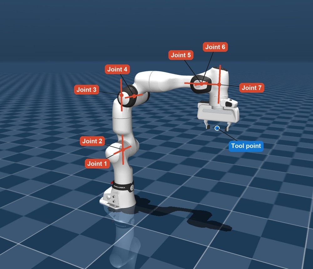
The Jacobian connects the two
Rather than solving for a final pose, the arm works in small steps, at the level of speeds. The Jacobian J(q) is a table with 3 rows and 7 columns. Each column says how fast the tool moves in x, y and z when that joint turns at 1 rad/s, in the current pose.
For a rotating joint, each column has a simple meaning, which is axis × (tool − joint position). MuJoCo calculates this directly from the arm's model. The table changes as the arm moves, so it's worked out again at every step.
Differential IK: going backwards
The controller decides a tool velocity, heading to the goal: ẋ = 2 (goal − tool), at no more than 0.3 m/s. Going back to joint speeds needs an inverse of J, which isn't square. So I use the damped pseudo-inverse:
J⁺ ẋgives the smallest joint speeds that produce the wanted tool velocity.- Damping
λ(0.03) keeps things under control at singular poses, such as a fully stretched arm, where a tool direction can't be reached and plain inversion would demand huge speeds. The price is that the tool follows its path a little less exactly. (I − J⁺J)is the null space: joint motion that, in principle, doesn't move the tool at all. These are the spare joints. I use them to pull the arm gently towards a comfortable home pose, so it doesn't drift into a strange shape.
Moving the safety rules to the joints
Here's why the Jacobian matters for safety. The rules are about the tool's position, and the filter chooses joint speeds. The chain rule connects them:
It's the same straight-line rule as Step 4, now across 7 numbers instead of 2. The QP doesn't care: it's still a bowl with straight-line limits. Joint limits go in the same way, with each joint getting its own barrier 0.05 rad inside its limit.
# The Python version of the rule for each shape
h, a = rule.shape.value_and_gradient(tool_position)
row = a @ J                                   # a · J(q)
limit = rule.caution * h * abs(h)             # alpha(h)
# Then the solver finds u closest to u_cmd, with row · u >= -limit
Step 8Protecting the whole arm, and keeping the cup upright
Rules on one point leave the rest of the arm unprotected. In my test, a tool-only filter let the arm's body pass 8.7 cm into a pillar while it saw no problem.
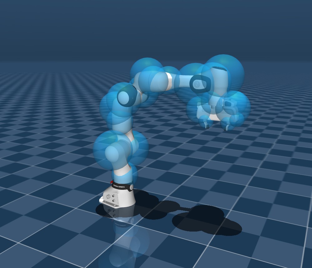
Spheres: a sphere is the easiest shape to check. The trick is to grow each object by the sphere's radius, plus 1 cm, then treat the sphere's centre as a point. The same rule then applies, using that sphere's own Jacobian.
Self-collision: the arm can hit itself, so pairs of spheres at least 3 links apart get a rule to stay apart.
The counter: spheres also stay above the work surface.
Keeping the cup upright
Staying out of a region says nothing about tilt. The paper adds a rotation penalty to the QP's cost, where e is the rotation needed to get back to the starting orientation, and Jr is the rotation part of the Jacobian:
It's a soft cost, not a hard rule, so it doesn't guarantee a tilt limit. One thing I had to add: with this penalty and a position-only command, the arm stalled. The command asked for rotation, and the penalty removed it, so the two fought. Using a 6-D command that also asks to hold orientation fixed it. The paper doesn't say how its commands treat orientation, so this may differ from its setup.
All togetherThe full filter
Every piece above is one line of this problem, solved 45 times a second:
| Idea | Plain meaning | Where it appears |
|---|---|---|
Barrier function h | One number for how safe a position is | Each rule |
| Superquadric | A smooth shape around an object or region | Gives h and a |
Approach limit α(h) | Slow down near the boundary | Right side of each rule |
| QP | Smallest change obeying every rule | The whole problem |
Jacobian J | Joint speeds to tool speed | Left side of each rule |
| Differential IK | Tool velocity to joint speeds | Makes u_cmd |
| Semantic rule | Which regions apply, for what's held | Chooses the rules |
Next: how I tested all this, and what the numbers showed.
Go to Practices